My intent in this article is to help engineers to gain more insight about Fourier Transform by emphasizing the geometrical aspect of the transform. I only consider the discrete case, where data is sampled and is of finite length. Besides its ubiquitous appearance in practical situations, finite discrete data is easier to work with. To treat the infinite case (whether discrete or continuous), we need concepts from the field of Functional analysis which may be quite complex and will probably distract the reader.
I show here that the Discrete Fourier Transform (DFT) of a signal represents the same signal in a rotated coordinate system embedded in the complex mathematical space ![]() . This representation is definitely not new, but is usually not emphasized in typical engineering curricula. In my personal opinion, it is very helpful in strengthening that signals can be considered as an entity and its time domain image is just one (convenient) representation.
. This representation is definitely not new, but is usually not emphasized in typical engineering curricula. In my personal opinion, it is very helpful in strengthening that signals can be considered as an entity and its time domain image is just one (convenient) representation.
We consider a sampled data, possibly collected through measurement. The data will be labelled as follows
(1) ![]()
The data can be visualized to be a vector ![]() in the complex space containing all
in the complex space containing all ![]() tuples
tuples ![]() . Note that we used a zero indexing to label the data sequence. Usually
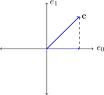
. Note that we used a zero indexing to label the data sequence. Usually ![]() is a sequence of real numbers. The figure below shows
is a sequence of real numbers. The figure below shows ![]() in the two dimensional space.
in the two dimensional space.

The sampled data ![]() appears in the \emph{natural} coordinate system
appears in the \emph{natural} coordinate system ![]() , where
, where ![]() and
and ![]() . In a general space
. In a general space ![]() , there are
, there are ![]() such vectors
such vectors ![]() ,
,
![Rendered by QuickLaTeX.com \begin{align*} \mathbf{e_0}&=[1, 0, \cdots, 0]\\ \mathbf{e_1}&=[0, 1, \cdots, 0]\\ \vdots\\ \mathbf{e_{N-1}}&=[0, 0, \cdots, 1]. \end{align*}](http://samehelnaggar.ca/wp-content/ql-cache/quicklatex.com-e90bddff92797e65eeb1f5e9f514be0d_l3.png)
In the 2D case, a simple signal ![]() can be represented in terms of
can be represented in terms of ![]() and
and ![]() as
as
(2) ![]()
The signal strengths ![]() and
and ![]() can be interpreted as the projections of the vector
can be interpreted as the projections of the vector ![]() onto
onto ![]() and
and ![]() .
.
As I will discuss in a different article, an important class of dynamic systems is the class of linear time invariant systems. The response of these systems can be described convolving the signal ![]() with the impulse response. Additionally, for a discrete system the convolution operation can be described by a circulant matrix (operator). Circulant matrices have a very interesting property: they all have eigenvectors that form another basis (coordinates in
with the impulse response. Additionally, for a discrete system the convolution operation can be described by a circulant matrix (operator). Circulant matrices have a very interesting property: they all have eigenvectors that form another basis (coordinates in ![]() \{
\{![]() that can be written as
that can be written as
![]()
It can be shown that such set indeed form a complete orthonormal basis. As usual, the inner product of two vectors ![]() and
and ![]() is defined as
is defined as
(3) 
where ![]() is the complex conjugate of
is the complex conjugate of ![]() .
.
As mentioned above, the set ![]() forms an orthonormal basis that spans
forms an orthonormal basis that spans ![]() . This means that we can equally express any signal (
. This means that we can equally express any signal (![]() for example) as a linear combination of the set
for example) as a linear combination of the set ![]() . Therefore, we can write
. Therefore, we can write
(4) 
The coefficients ![]() appearing in the above equation are nothing but the projections of
appearing in the above equation are nothing but the projections of ![]() onto the coordinates
onto the coordinates ![]() .
.
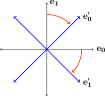
In 2D, ![]() and
and ![]() become
become
![Rendered by QuickLaTeX.com \begin{align*} \mathbf{e_0'}&=\frac{1}{\sqrt{2}}[1, 1]\\ \mathbf{e_1'}&=\frac{1}{\sqrt{2}}[1, -1], \end{align*}](http://samehelnaggar.ca/wp-content/ql-cache/quicklatex.com-1e97f240efeda45e8cb62667983a1e7a_l3.png)
which is equivalent to rotating ![]() and
and ![]() by -45 degrees as shown below
by -45 degrees as shown below

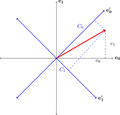
In ![]()
![]() are complex. Please see the figure below
are complex. Please see the figure below

To find ![]() appearing in (4) we use the important concept that
appearing in (4) we use the important concept that ![]() is a unique entity regardless of the representation. This means that
is a unique entity regardless of the representation. This means that
(5) 
We then exploit the orthogonality of the different ![]() and take the inner product of both sides of the above equation by
and take the inner product of both sides of the above equation by ![]() . This means that all the terms at the right hand side vanish except for
. This means that all the terms at the right hand side vanish except for ![]() . Therefore,
. Therefore,
(6) 
Note that ![]() unless
unless ![]() . Therefore it is straightforward to show that
. Therefore it is straightforward to show that
(7) ![]()
Therefore, we can write ![]() as
as
(8) 
The above expression is precisely the discrete Fourier transform (DFT) of the sequence ![]() ‘. From a geometric point of view, it is the formula to calculate the components of the vector
‘. From a geometric point of view, it is the formula to calculate the components of the vector ![]() onto the coordinate system
onto the coordinate system ![]() . Therefore,
. Therefore,
The projections of ![]() in the
in the ![]() coordinate system represent the original sequence, while the projections in the
coordinate system represent the original sequence, while the projections in the ![]() system are the DFT components.
system are the DFT components.
In 2D, the relation between the signal and its DFT can be plotted as shown below

Plancherel and Parseval’s theorem
The norm of the vector ![]() is an invariant quantity. This means that it does not depend on the coordinate system. Accordingly
is an invariant quantity. This means that it does not depend on the coordinate system. Accordingly
(9) 
which is known as Plancherel theorem. Similarly the inner product of any two vectors ![]() and
and ![]() in
in ![]() is invariant. Therefore,
is invariant. Therefore,
(10) 
which is Parseval’s theorem.
Uncertainty Relation
One of the most important properties of Fourier transforms is the uncertainty principle. The uncertainty principle is a fundamental concept in Quantum mechanics.
Assume for now that ![]() . Geometrically this means that
. Geometrically this means that ![]() is in the direction of the basis vector
is in the direction of the basis vector ![]() and orthogonal to other
and orthogonal to other ![]() , where
, where ![]() . Using \label{eq:dft}, it is easy to show that such vector has projections of equal strength in the
. Using \label{eq:dft}, it is easy to show that such vector has projections of equal strength in the ![]() coordinate system. This means that being aligned with one of the coordinate axes of
coordinate system. This means that being aligned with one of the coordinate axes of ![]() (localized) implies that
(localized) implies that ![]() is “equally distributed” over
is “equally distributed” over ![]() vectors. This is an emphasis of the uncertainty principle. In Quantum mechanics for example, if the particle state (think of it as the vector
vectors. This is an emphasis of the uncertainty principle. In Quantum mechanics for example, if the particle state (think of it as the vector ![]() ) is aligned with one of the vectors that represent position (the
) is aligned with one of the vectors that represent position (the ![]() system of coordinates) then its momentum (the Fourier transform of position ) has equal projections onto all
system of coordinates) then its momentum (the Fourier transform of position ) has equal projections onto all ![]() and hence not determined.
and hence not determined.
PDF version of the current article: Fourier Transform.